PHOTON TACHYON
Once signal paths have been tested and Displays properly identified (see Signal Routing and Display Identification in Setting Up a Show), it is time to calibrate outputs.
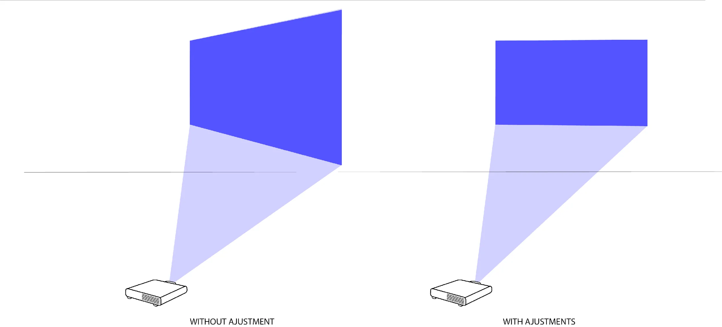
Manual 2D keystone calibration is the simplest form of calibration offered in TACHYON or PHOTON. It should be used in cases where video content is projected onto flat surfaces or displayed on video monitors. By manipulating the four corners of a Screen within a Virtual Display, the user can position them in relation to the four corners of a Display (corner-pin). This method can also be used to correct the trapezoidal distortion of an image caused by a difference in angle between the alignment of a real-world projector and projection surface (keystone correction).
Add a Projector in the 3D Scene
In order to start the calibration process, you will need a virtual representation of the real-world display. If you are attempting a manual keystone calibration, the appropriate Virtual Display type is a Projector (even if you are attempting to calibrate a video monitor such as a TV).
Make sure the Virtual Video Output that corresponds to the Video Output Port was declared in the Settings module when you created your project’s Network Group. If this wasn’t done, please do so before continuing (see Virtual Video Outputs Creation in Setting Up a Show).
Automatic Virtual Output Creation
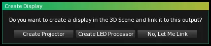
When a Virtual Video Output is declared in the Settings module, a confirmation box opens and displays the following message: “Do you want to create a display in the 3D Scene and link it to this output?” By clicking the Create Projector button you will automatically add a Projector in the 3D Scene linked to the new output.
Manual Projector Creation
If for any reason you created a Virtual Video Output but did not assign a Projector to it, you will have to follow these steps:
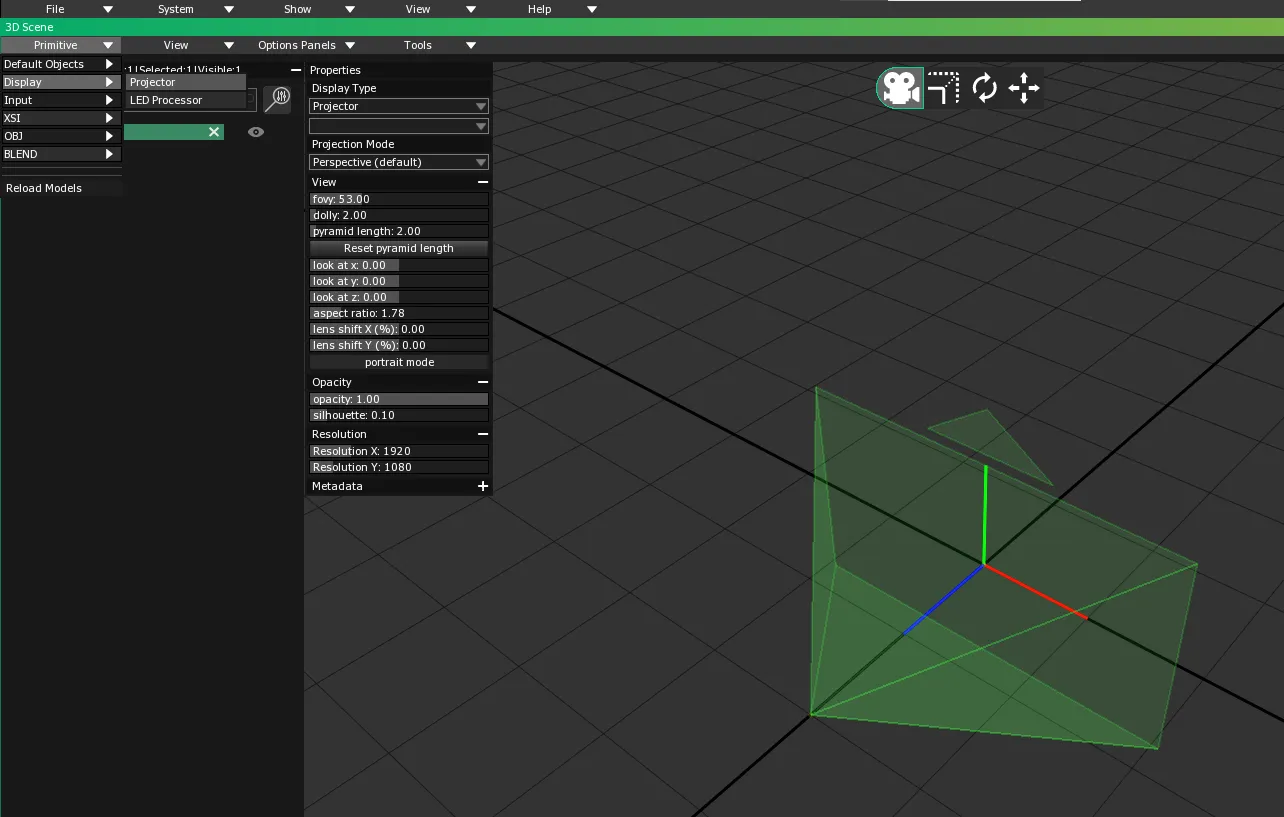
- In the 3D Scene module, select to create a new Projector. A new entry (named Projector) will appear in the Scene Primitives list. A pyramid, representing the light beam emitted by the Projector, will also be visible in the 3D Scene Preview.
- In the Settings module, go to the TACHYON or PHOTON Selection list and select the server you want to use as an output for the video signal.
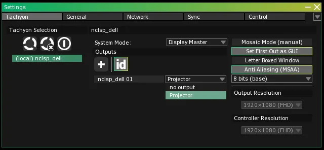
- Beside each of the Virtual Video Outputs you created, you will find a dropdown menu with the
no output option selected. Using the dropdown menu linked to the appropriate Virtual Video Output, select the Projector you created.
Renaming a Projector
Once a Projector in the 3D Scene is linked to a Virtual Video Output, you can rename it to make it easier to identify. (In complex projects involving many Displays, renaming Projectors is a must-do.)
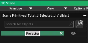
Double-click on the Projector’s entry in the Scene Primitives list. A text field will appear allowing you to enter a new name for the Projector.
Add a Plane in the 3D Scene
For a manual 2D calibration the Projection Surface is necessarily a plane. This plane can represent a video monitor (a TV screen, for example) or a wall upon which video content will be projected.
- To add a plane to the 3D Scene, select in the Primitive dropdown menu.
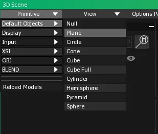
The plane will appear in the Scene Primitives list, and a visual representation of it will appear at the origin (0,0,0) of the 3D Scene Preview.
Many ready-to-use 3D objects are available in TACHYON or PHOTON. They can act as Projection Surfaces and simplify the construction of the virtual representation of your real-world stage space. 3D objects can be selected from the Primitive dropdown menu .
Scale, Translate and Rotate the Plane
It is possible to modify the shape of the plane in order to match the ratio of the real-world display it represents. You can also position and rotate the plane in space to match the position and orientation of the real-world display.
Scaling, positioning and orienting are crucial in stage contexts where many real-world projectors cover many Screen Surfaces. Under these circumstances, it is important to accurately represent the spatial relations between all objects in TACHYON or PHOTON’s virtual world. If the spatial relations between objects aren’t accurately represented it won’t be possible to complete the calibration process.
Scaling, positioning and orienting are not crucial in stage contexts involving single Displays linked to single Screen Surfaces that act as autonomous pairs. However, doing so is considered a best practice and will give you access to a realistic pre-visualization of the project.
Project pre-visualization is one of TACHYON or PHOTON’s key features. VYV’s software can create full 3D simulations of the real-world stage space. In the 3D Scene module Screen Surfaces (with their video content), Displays, lighting equipment, and set elements can be placed in a virtual space that provides a complete overview of a project.
An object’s size, position or orientation (Decorative Objects as well as Projection Surfaces) in the 3D Scene can be modified using the Transformations Panel or Transformation Manipulators.
The Transformations Panel contains multiple sliders that allow the modification of the Scale, Translate and Rotate parameters for each axis (X, Y and Z) for any object previously created in the 3D Scene module.
- Select the object you want to alter by clicking on its entry in the Scene Primitives list.
- To open the Transformations Panel, press T on the keyboard OR select in the 3D Scene’s main menu.
- To change the geometric coordinates of an object, adjust the value of the sliders. You can adjust the value of a slider by manipulating it with a
Click+Drag, or you can Double-click on it to open a text field where you can enter a desired numeric value.
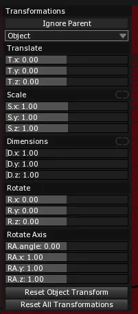
The effects of these transformations can be seen in the 3D Scene Preview. The graphic representation of the selected object will be modified as well.
Slider values differ depending on the parameters they represent. The Scale sliders are not dimension sliders; they act as scaling coefficients applied to the object’s original size.
Example: If the scale value of a cube featuring edges of 2 meters is changed from 1 to 4 on all three axes, the cube will now have edges of 8 meters. The Translate sliders express a value in meters.
The Rotate sliders express values in angles. And the Rotate Axis sliders are used to apply a rotation expressed in an angle that corresponds to specific vectors.
Example: An angle is set with the first slider while the three other sliders represent vector values for each axis that will determine how the rotation will be applied to each.
The Transformation Manipulators facilitate direct modification of a 3D object’s parameters —Scale, Translate, Rotate — by manipulating your mouse in the 3D Scene Preview.
Enable the desired Transformations Manipulator using the following methods:
- Scale Manipulator:
- Press X on the keyboard OR click on the Scale button located in the top-right corner of the 3D Scene window.
- Translate Manipulator:
- Press V on the keyboard OR click on the Translate button located in the top-right corner of the 3D Scene window.
- Rotate Manipulator:
- Press C on the keyboard OR click on the Rotate button located in the top-right corner of the 3D Scene window.
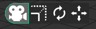
The Transformation Manipulators will appear when a 3D object is selected.
TACHYON or PHOTON’s Manipulators feature a standard color scheme for their 3D coordinate system: X is red, Y is green and Z is blue.
Click+Drag the handle of the axis parameter you want to modify (X, Y or Z). The handle will become yellow when selected.- The Scale and Translate Manipulators feature a yellow dot at the intersection of their axes.
Click+Drag the yellow dot to simultaneously apply transformations to all axes.
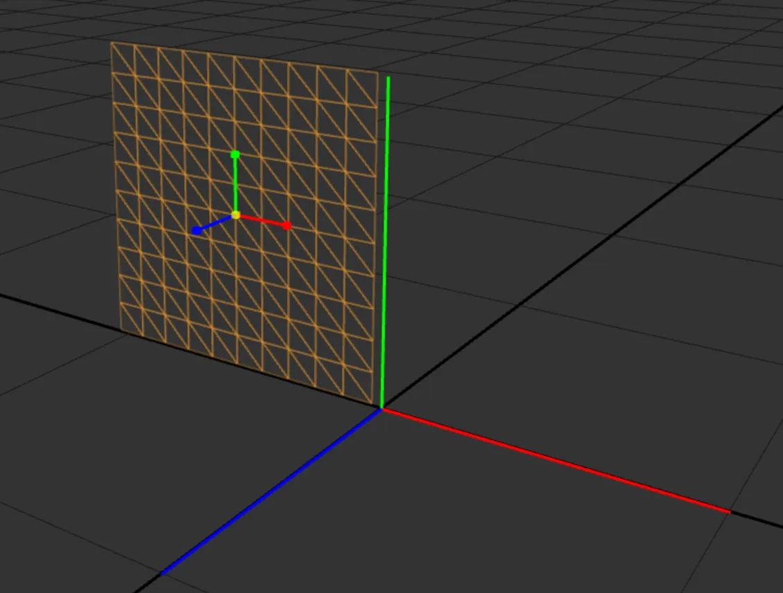
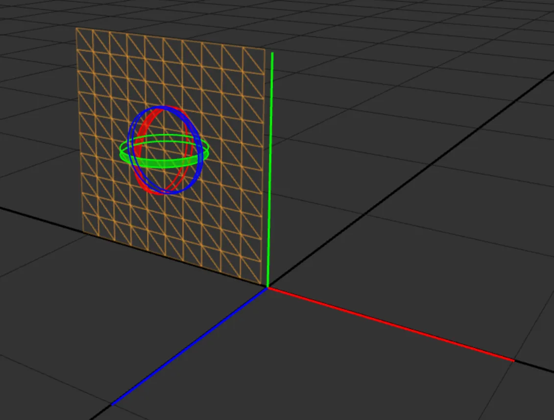
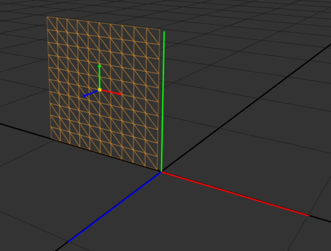
Warning:Enabling a Manipulator will disable camera movements in the 3D Scene Preview. To switch back to camera control, press S on the keyboard OR click the Camera button located at the top-right corner of the 3D Scene.
If you want to control the camera while a Manipulator is enabled, press and hold S on the keyboard. This will allow you to manipulate the camera.
To switch back to Manipulator control, release the S key.
Map the Plane to the Display
Once the plane that acts as the Projection Surface has undergone the appropriate geometric transformations, you have to add it to the Mapped Objects list.
In order to calibrate a Display (find its position and orientation in the real world), TACHYON or PHOTON has to build geometric correspondences with at least one 3D object representing a physical structure in the real world. In this case, the plane will act both as a Projection Surface and a Mapped Object.
- Select the 3D Scene module’s Calibration mode by pressing 2 (TACHYON) or 4 (PHOTON) OR by clicking on the
Calibration button located at the top-right corner of the 3D Scene window.

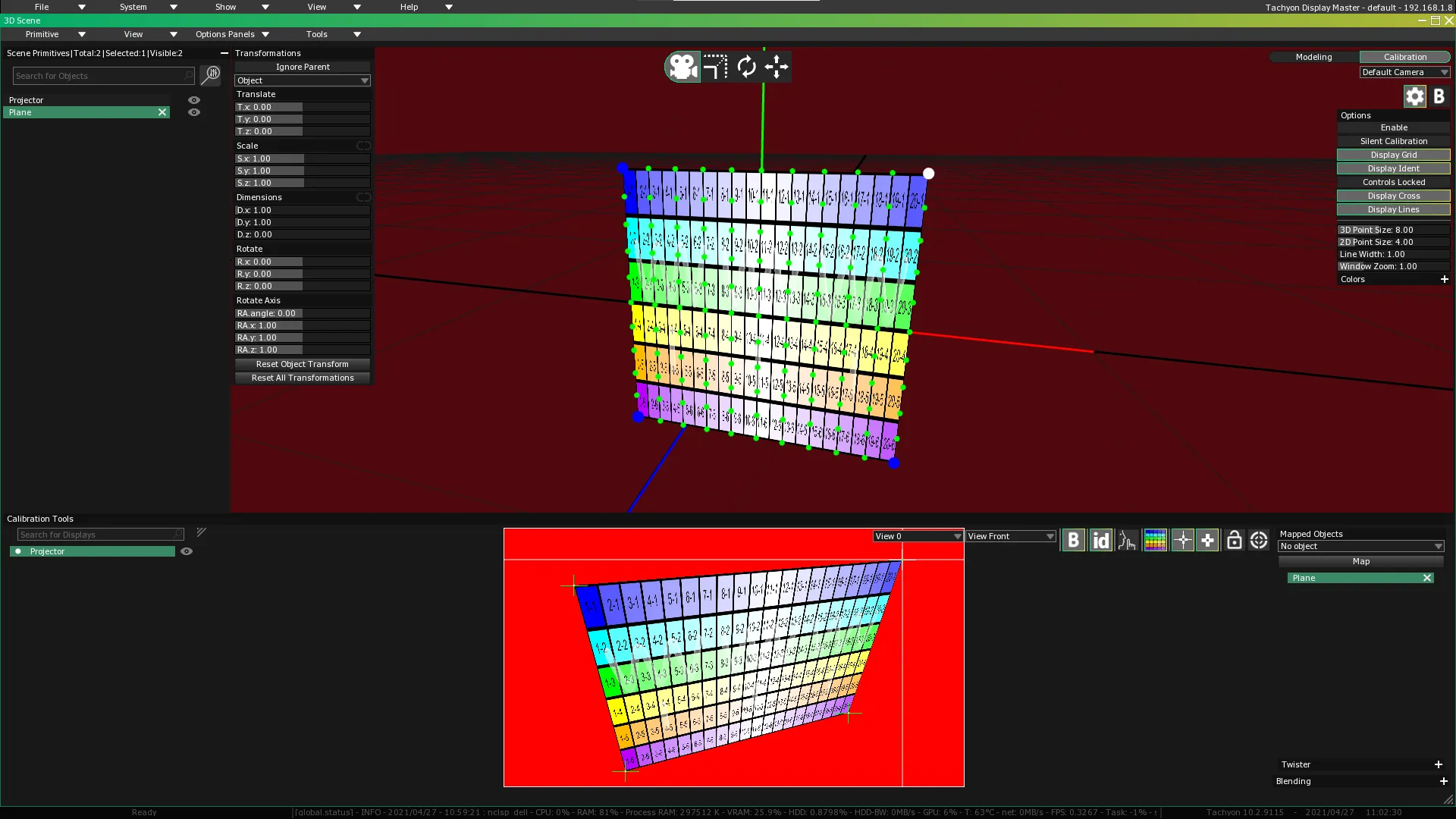
Once the Calibration mode is enabled, the 3D Scene Preview will turn red and the Calibration Tools Window will open in the lower part of the 3D Scene window.
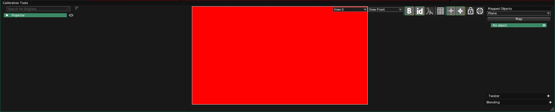
- Select the Display you want to calibrate by clicking on its entry in the Calibration Tools Window list. (If you haven’t renamed the Display, it will be listed as “Projector.”)
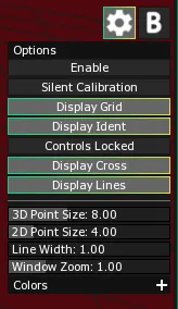
Warning:Make sure the Display Grid is enabled. By showing a representation of how the Display’s texture map is distributed (both in the 3D Scene Preview and in the real-world projection), the Display Grid will let you preview the amount of distortion affecting the projected image. Normally, you will try to limit distortion as much as possible by manipulating the Calibration Points.
-
Press D OR click on the gear icon button to access the 3D Scene module’s Settings menu and click on the Display Grid toggle if the Display Grid isn’t already activated OR use the display grid toggle in the quick option bar:

-
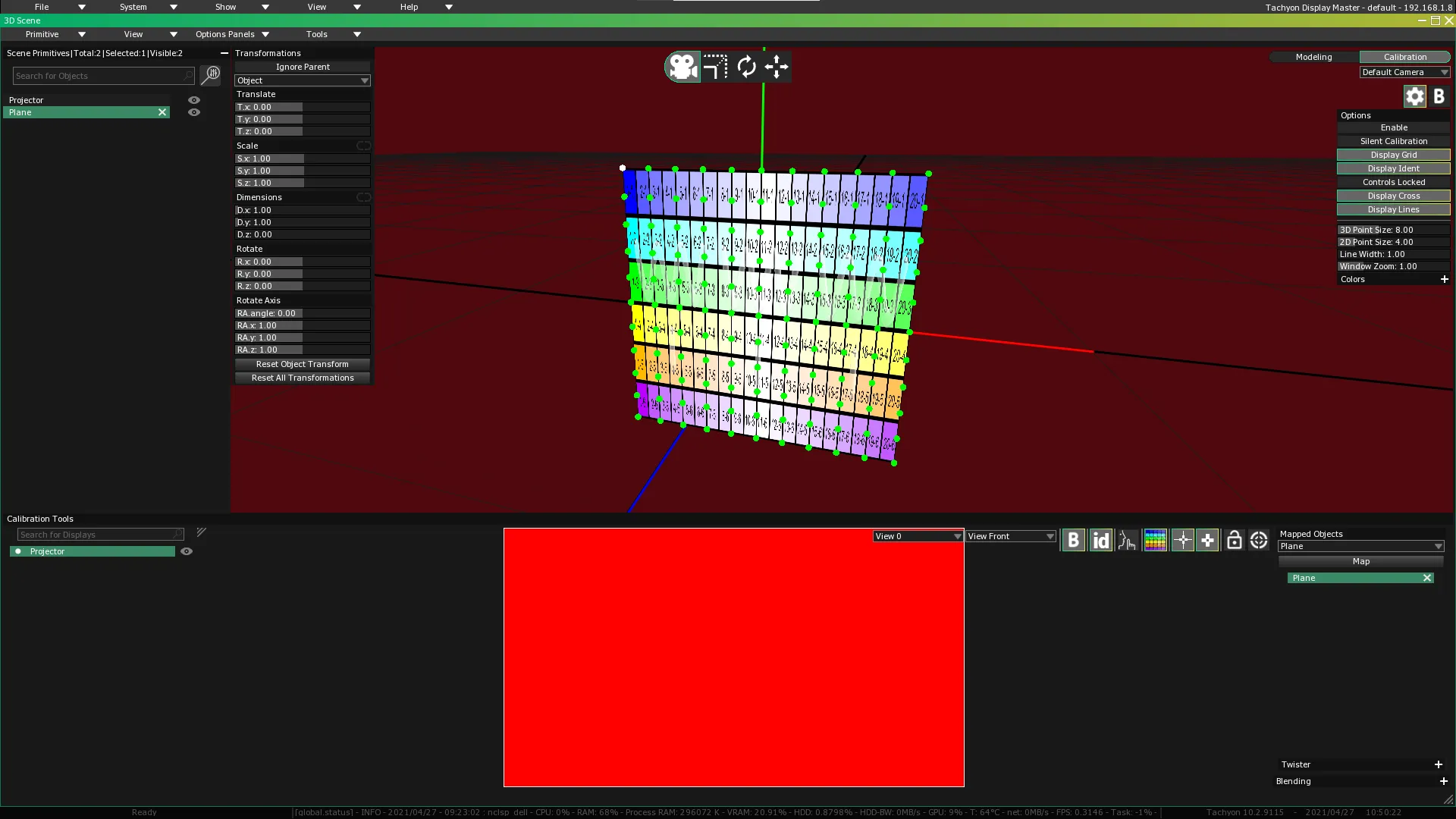
In the Mapped Object window section (right of the Calibration Tools Window), select the plane from the Model Selection dropdown menu.
-
Click on the Map button to add the plane as a Mapped Object.
The plane will be covered by green dots corresponding to its vertices in the 3D Scene Preview.
- Multiple 3D objects can be added as Mapped Objects for the same Display. This allows the Display to simultaneously support multiple calibrations.
Example: In a case where a single video projector covers two different Screen Surfaces, each Screen Surface would be represented by a 3D object, and both 3D objects would have to be added as Mapped Objects to the same Display (representing the video projector).
- A single 3D object can be added as a Mapped Object for multiple Displays.
Example: In a situation where beams of light from multiple projectors fall on a single Projection Surface, the same 3D object (corresponding to the Projection Surface) would have to be added to each of the Displays (corresponding to the video projectors).
Calibration Point Creation and Manipulation
In order to calibrate the Display, you will have to create four Calibration Points that match the four corners of the plane. You will then manipulate these Calibration Points until the image being displayed isn’t distorted.
Calibration Point Creation
Calibration Points are created by converting vertices: the green dots that correspond to the 3D object’s vertices. This is done through a Ctrl + Double-click applied to a vertex.
To perform a manual 2D keystone calibration, you will have to create Calibration Points using the four corners of the plane.
- Ctrl +
Double-click sequentially on the four vertices that match the four corners of the plane.
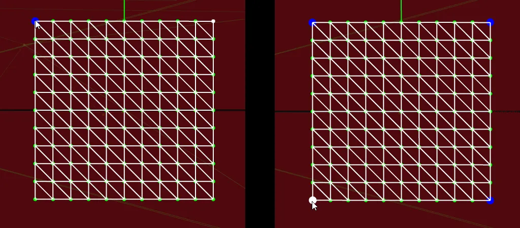
Whenever a vertex point is converted to a Calibration Point and is selected, it will double in size and turn white. An unselected Calibration Point will retain this double size but will turn blue.
Once the four Calibration Points have been created, the plane displayed in the Calibration Tools Window will snap to its four corners and completely fill its space.
If you want to use the full pixel space offered by the Display and there isn’t a need for any kind of geometric correction (if you plan to output the signal to a video monitor, for example), you are done.
Calibration Points, Crosses and Lines
Whenever a Calibration Point is created, a green cross will appear in the Calibration Tools Window Preview where it is positioned. The green cross will also be projected by the Display it is linked to. If the Calibration Point is moved, the cross will also move to reflect the change of position.
If the Calibration Point is selected, its corresponding green cross will feature elongated white lines that will extend until they reach the edge of the projected image.
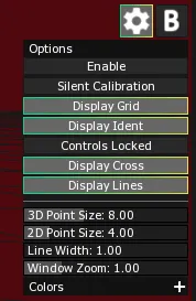
These two features — green crosses and white lines — should help you calibrate the Display. Parameters for both the crosses and the lines are accessible in the Options menu. If you want to modify these parameters, click on the gear icon button to access the Options Panel and manipulate the following widgets:
- Display Cross toggle:
Click on the toggle to show/hide the green crosses.
- Display Lines toggle:
Click on the toggle to show/hide the white lines.
- 2D Point Size slider:
Click+Drag the slider to change the size of the green crosses.
- Line Width slider:
Click+Drag the slider to change the width of the white lines.
Manipulating Calibration Points
If you have to apply 2D geometric corrections (such as keystoning) to the video output, you will have to manipulate the Calibration Points. By moving Calibration Points in TACHYON or PHOTON you will alter the projected image’s geometric coordinates and compensate for alignment differences between a Projector and its related Projection Surface.
Calibration Points will have to be selected and moved one by one from those that were previously declared. This step has to be repeated with each of the previously declared Calibration Points (a keystone correction will involve four Calibration Points). The final positions of the Calibration Points in the projected image (on the real-world Projection Surface) will make it possible to project an accurate (geometrically correct) image.
Calibration Points can be manipulated by using the keyboard on its own, or by using a combination of the mouse and keyboard.
Keyboard Calibration Point Manipulations
- Select Previous/Next Calibration Point
- Page Up selects the previous Calibration Point.
- Page Down selects the next Calibration Point.
- Move the Calibration Point that is Currently Selected
- Arrows move the selected Calibration Point in any of the four directions represented by the arrow keys.
- Shift + Arrows applies the same effect as above, only 10 times slower.
- Ctrl + Shift + Arrows applies the same effect as above, only 100 times slower.
- Move the Entire Calibration
- Alt + Arrows moves all of the Calibration Points at the same time.
- Alt + Shift + Arrows applies the same effect as above, only 10 times slower.
- Add/Remove a Calibration Point
- - removes the Calibration Point that is currently selected.
- + adds a new Calibration Point corresponding to the vertex that is currently selected, or re-adds a previously deleted Calibration Point.
Mouse and Keyboard Calibration Point Manipulations
- Select a Calibration Point from the Calibration Tools Window Preview
- Ctrl +
Left-click selects the Calibration Point that is closest to your cursor and moves it to where you have clicked.
- Select a Calibration Point in the 3D Scene Preview
- Ctrl +
Left-click on a Calibration Point (blue dots) to select it (it will turn white).
- Cycle Through Calibration Point Selection
Mouse wheel : Place the mouse over the Calibration Tools Window Preview and use the mouse wheel to cycle through the previously declared Calibration Points.
- Move a Calibration Point
Left-click anywhere in the Calibration Tools Window Preview to move the selected Calibration Point to its new location.Left-click+Drag anywhere in the Calibration Tools Window Preview to move the selected Calibration Point in the direction that you drag the mouse.- Shift +
Left-click+Drag applies the same effect as above, only 10 times slower.
Add/Remove a Calibration Point
- Ctrl +
Double-click on a vertex (green dots) on the Mapped Object in the 3D Scene Preview to create a new Calibration Point.
- Ctrl +
Right-click on a Calibration Point to remove it.
Freezing an object’s Transformations sets its current size, orientation and location as the new default values without modifying the object’s geometric coordinates.
Freeze an Object
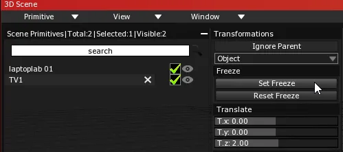
- Select the object by clicking on its entry in the Scene Primitives list.
- To activate the Transformations Panel press T on the keyboard OR select in the 3D Scene main menu.
- Click on the
Set Freeze button located at the top of the Transformations Panel.
- If you want to revert to the object’s initial parameters, you can unfreeze it by clicking on the
Reset Freeze button located at the top of the Transformations Panel.
Why Freeze?
Freezing an object sets its Calibration Points directly in relation to its new position in the 3D Scene Preview. Calibration Points are created out of a 3D object’s vertices and are the main features used during the calibration process. Therefore, it is crucial to alert the software through the Set Freeze command if a 3D object’s geometric parameters have been modified before starting the calibration process.
Furthermore, 3D objects in PHOTON can be linked to position and orientation data (provided by stage automation and tracking or animations). These 3D objects will move in the real world but you will want to retain their original geometric data for the purposes of display calibration. Freezing makes this possible, and facilitates accurate projection on surfaces that move.